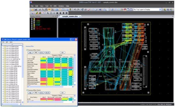
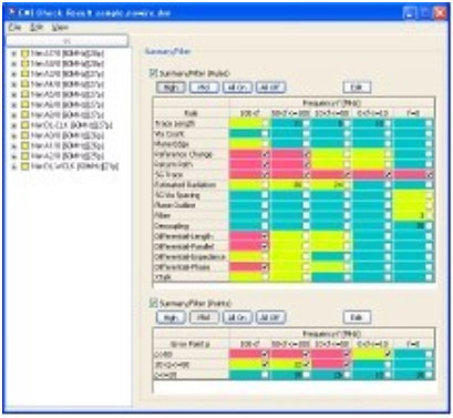
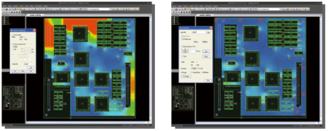
EMIStream

EMIStream is an EMI suppression support tool developed by NEC that can decrease undesirable EMI generated from PCB at an early design stage.

EMI_design_rule

EMI Design Rule Check scans your board against 15 rules and lists errors in order of priority, allowing time-efficient noise countermeasures. Power/ Ground Resonance Analysis shows you the hot spots on the board, enabling optimized capacitor placement to reduce resonance.

Major electronics manufacturers worldwide, including NASA, are using EMIStream to significantly decrease the time and cost spent on the design and evaluation process.

SIMATIC IT R & D Suite

EMIStream is an EMI Design Rule Check and Plane Resonance Analysis tool that can suppress undesirable EMI generated from PCB. By eliminating possible EMI issues at the initial design stage, EMIStream will improve efficiency, significantly decrease time spent on the evaluation process, and enable rapid time-to-market.

Many choose to use EMIStream for its user-friendly interface, easy 4-step setup, speedy analysis, and seamless work flow with multiple CAD layout interfaces.

EMI_design_rule_check

EMI Design Rule Check

This function provides advice related to scanned components, traces, and plane location. EMIStream's 15 rule check items are boiled down from a huge amount of historical know-how about EMI suppression countermeasures and have been verified by NEC Laboratory and local and overseas university researchers with a logical background. In this way, EMIStream utilizes the most valuable items for real-world PCB design.

15 Rule Check Items

Return Current Path Discontinuity Check

  • Reference Change
  • Return Current Path Discontinuity
  • Traces Near Plane Edge
  • SG Trace
  • SG Via Spacing

Power Plane Check

  • Grounding Vias Along Plane Outline
  • Decoupling Capacitor
  • Digital/Analog Interference Check
  • IC Ground Split Check

Trace Check

  • Trace Length
  • Via Count
  • Estimated Radiation
  • Filter
  • Differential Signal
  • XTalk
error_filtering

Error Filtering

This function allows you to filter errors and hone in on critical problems relevant to your design. The Design Rule list lets you look at certain rules of your choice as well as narrow down the frequency range (of the nets). The Error Point list is organized by number of error points, which also gives you the frequency range columns. You can customize the frequency and error point ranges.

emicheckreport

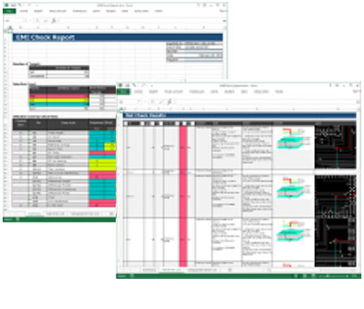
EMI Check Report Function

You can export EMI Check results in an Excel format. It displays the error, the location on PCB, and advice on how to fix the problem. This is very useful when sharing results with fellow engineers or an outsourcing design bureau. You can edit comments and customize the report to fit your needs.


est-radiation

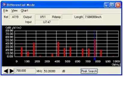
Estimated Radiation Value Graph Display

The frequency spectrum chart display of estimated radiated electromagnetic field allows you to see the problematic frequency range at a glance. The Expert Option lets you to set the IC rise time and damping/termination resistor value for individual nets and override the global value that is set in the parameter. By putting in specific parameters for nets, you can get more accurate results.

power-ground

Power/ Ground Resonance Analysis

EMI increases if resonance occurs between the power/ground. The Power/ Ground Resonance Analysis Function takes into account plane shapes, capacitors, and distance between the power/ground planes to analyze resonance based on the PEEC (Partial Element Equivalent Circuit) method.

emi-calculation

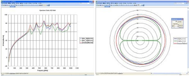
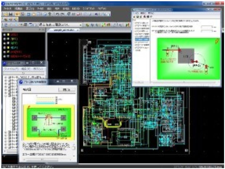
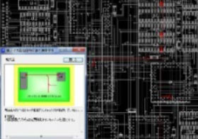
Far Field EMI Calculation

Far Field EMI is calculated by plane edge voltage (one pair of ground and power). It displays far field horizontal/vertical frequency characteristics and an azimuth pattern. You can adjust the calculation environment, such as the position of the PCB on the turntable, the distance to the antenna, and the antenna height.


multi-layer

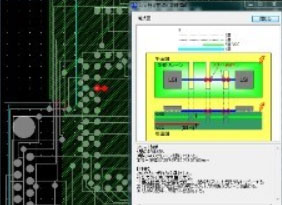
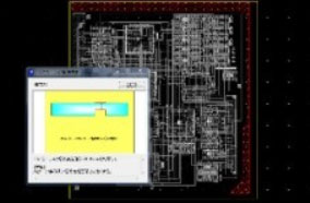
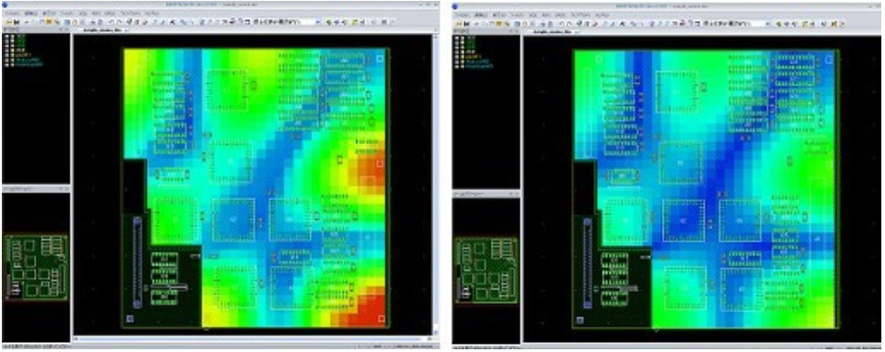
Multi-layer Resonance Analysis

You can analyze multiple layers at a time. It is possible to reduce resonance by changing capacitor placement, and now EMIStream allows you to take via placement into account and change/add locations as needed.


resonanceanalysis

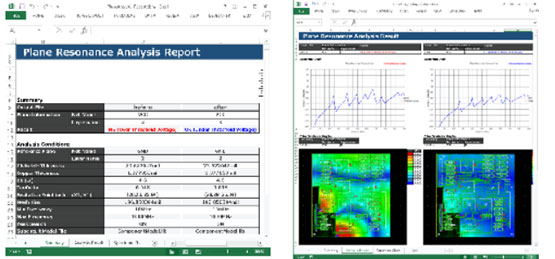
Resonance Analysis Report

Resonance analysis results such as analysis conditions, spectrum chart and voltage-distribution color gradation maps are reported collectively in an Excel format.

Two or more analysis results, such as results of before / after adding capacitors or analysis results of all power planes on boards, can be reported collectively. These Reports can be preserved as evidence.

esd-rule

ESD Rule Check

A discharge can occur when an electrically charged object (including the human body) touches an electronic device. This phenomenon called ESD (Electrostatic discharge) causes malfunction and failure of electronic devices.

EMIStream ESD Rule Check Feature will detect areas where ESD tolerance levels are low on a PCB and offer suggestions for solutions.

Check rules and threshold values are based on real-world cases from companies around the globe and are verified through research at NEC Lab. Possible ESD problems are detected at an early design stage, thus decreasing time spent on evaluation processes. Import the CAD layout data, complete a simple set-up, and you are ready to run ESD Rule Check. Factors causing ESD are instantaneously pointed out, enabling you to take immediate action to solve the problems.

10 Rule Check Items

ESD Rule Check Feature includes Signal Trace, Component Placement Validity, and FG Pattern Check Groups consisting of ten key check rules.

Signal Trace Check Group

  • Traces Near Plane Edge
  • Traces crossing over power and ground plane
  • Signal trace over the slit of the ground/power plane

    signal_trace

    If a signal trace is crossing over the slit of the ground/power plane, it causes ESD noise on signals. This check will detect such structural problems and displays a warning message.

  • SG Trace
  • SG Via Spacing
  • Power Protection

Component Placement Validity Check Group

  • Input Pin Protection
  • Power Pin Protection
  • Reset Line Protection

    reset_line_protection

    Even though noise suppression components (such as capacitors) are added to the ESD sensitive signal trace or power source, they cannot effectively reduce ESD noise if they have not been properly placed. This check points out if the location of the component is not ideal and shows a warning message.

Trace Check

trace_check

The ESD noise flows into signal traces and power/ground planes if an FG pattern has an inadequate signal width or inappropriate via positions crossing over the layers.

In addition, the distance between the FG pattern and power/ground planes will affect the noise flow.

This check analyzes the FG pattern structure and its distance from power/ground planes and displays a warning message if there are any problems.